Phụ tùng máy nén khí Ingersoll Rand V Series 5-11kW

V SERIES 5~11KW
50 Hz OPERATION AND MAINTENANCE MANUAL
with parts catalogue
This manual contains important safety information and must be made available to personnel who operate and maintain this machine.
CCN.:47569128
REV:
DATE:
A MAR. 2016
Warranty
AIR COMPRESSOR GROUP
BONDED WARRANTY & REGISTERED START UP
The Company warrants that the equipment manufactured by it and delivered hereunder will be free of defects in material and workmanship for a period of twelve months from the date of placing the Equipment in operation or eighteen months from the date of shipment from the factory, whichever shall first occur. The Purchaser shall be obligated to promptly report any failure to conform to this warranty, in writing to the Company in said period, whereupon the Company shall, at its option, correct such nonconformity, by suitable repair to such equipment or, furnish a replacement part F.O.B. point of shipment, provided the Purchaser has stored, installed, maintained and operated such Equipment in accordance with good industry practices and has complied with specific recommendations of the Company. Accessories or equipment furnished by the Company, but manufactured by others, shall carry whatever warranty the manufacturers have conveyed to the Company and which can be passed on to the Purchaser. The Company shall not be liable for any repairs, replacements, or adjustments to the Equipment or any costs of labor performed by the
Purchaser or others without Company‘s prior written approval.
The effects of corrosion, erosion and normal wear and tear are specifically excluded. Performance warranties are limited to those specifically stated within the Company‘s proposal. Unless responsibility for meeting such performance warranties are limited to specified tests, the Company‘s obligation shall be to correct in the manner and for the period of time provided above.
THE COMPANY MAKES NO OTHER WARRANTY OR REPRESENTATION OF ANY KIND WHATSOEVER, EXPRESSED OR IMPLIED, EXCEPT THAT OF TITLE, AND ALL IMPLIED WARRANTIES OF MERCHANTABILITY AND FITNESS FOR A PARTICULAR PURPOSE, ARE HEREBY DISCLAIMED.
Correction by the Company of nonconformities whether patent or latent, in the manner and for the period of time provided above, shall constitute fulfilment of all liabilities of the Company for such nonconformities whether based on contract, warranty negligence, indemnity, strict liability or otherwise with respect to or arising out of such Equipment.
The purchaser shall not operate Equipment which is considered to be defective, without first notifying the Company in writing of its intention to do so. Any such use of Equipment will be at Purchaser‘s sole risk and liability.
CONTENTS & ABBREVIATIONS 1
CONTENTS ABBREVIATIONS & SYMBOLS
- CONTENTS #### Contact Ingersoll Rand for serial number
->#### Up to Serial No.
- FOREWORD ####-> From Serial
* Not illustrated
- DECALS T Option
NR Not required
AR As required
7 SAFETY SM Sitemaster/Sitepack
HA High ambient machine
9 GENERAL INFORMATION WC Watercooled machine AC Aircooled machine
ERS Energy recovery system
12 INSTALLATION / HANDLING T.E.F.C. Totally enclosed fan cooled motor (IP54)
O.D.P. Open drip proof (motor) (IP23)
17 OPERATING INSTRUCTIONS ppm parts per million
20 MAINTENANCE en
zh
English Chinense
23 TROUBLE SHOOTING
en
2 FOREWORD
|
The contents of this manual are considered to be proprietary and confidential to Ingersoll Rand and should not be reproduced without the prior written permission of Ingersoll Rand.
Nothing contained in this document is intended to extend any promise, warranty or representation, expressed or implied, regarding the Ingersoll Rand products described herein. Any such warranties or other terms and conditions of sale of products shall be in accordance with the standard terms and conditions of sale for such products, which are available upon request.
This manual contains instructions and technical data to cover routine operation and scheduled maintenance tasks by operation and maintenance staff. Major overhauls are outside the scope of this manual and should be referred to an authorised Ingersoll Rand service department.
All components, accessories, pipes and connectors added to the compressed air system should be:
. of good quality, procured from a reputable manufacturer and, wherever possible, be of a type approved by Ingersoll Rand.
. clearly rated for a pressure at least equal to the machine maximum allowable working pressure.
. compatible with the compressor lubricant/coolant.
. accompanied with instructions for safe installation, operation and maintenance
Details of approved equipment are available from Ingersoll Rand Service departments.
The use of non−genuine spare repair parts other than those included within the Ingersoll Rand approved parts list may create hazardous conditions over which Ingersoll Rand has no control. Therefore Ingersoll Rand does not accept any liability for losses caused by equipment in which non−approved repair parts are installed. Standard warranty conditions may be affected.
Ingersoll Rand reserves the right to make changes and improvements to products without notice and without incurring any obligation to make such changes or add such improvements to products sold previously.
The company accepts no responsibility for errors in translation ofthis manual from the original English version.
DECALS 3
ISO SYMBOLS
GRAPHIC FORM AND MEANING OF ISO SYMBOLS
|
|
||
| Prohibition / Mandatory | Information / Instructions | Warning |
|
4 DECALS
|
AUTOMATIC RESTART |
MAINTENANCE |
MAINTENANCE PROHIBITED |
|
COOLANT DRAIN |
CONDENSATE DRAIN |
FILTER |
|
FRAGILE |
KEEP DRY |
THIS WAY UP |
|
USE NO HOOKS |
NO SIDE CLAMPS |
HOURS |
|
Pinch point hazard. Keep hands clear. |
POWER |
INSPECT |
|
Every X months, if sooner than required by operating hours |
CHANGE / REPLACE |
CLEAN |
|
POWER INLET (AC) |
ANSI SYMBOLS
GRAPHIC FORM AND MEANING OF ANSI SYMBOLS
DECALS 5
INTAKE AIR. Can contain carbon monoxide or other contaminants. Will cause serious injury or death. Ingersoll Rand air compressors are not designed, intended or approved for breathing air. Compressed air should not be used for breathing air applications unless treated in accordance with all applicable codes and regulations.
HAZARDOUS VOLTAGE. Can cause serious injury or death. Disconnect power and bleed pressure from tank before servicing. Lockout/Tagout machine. Compressor must be connected to properly grounded circuit. See Grounding Instructions in manual. Do not operate compressor in wet conditions. Store indoors
RISK OF FIRE OR EXPLOSION. Electrical arcing from compressor components can ignite flammable liquids and vapors which can result in serious injury. Never operate the compressor near flammable liquids or vapors. If used to spray flammable materials, keep compressor at least 20ft away from the spray area.
HIGH PRESSURE AIR. Rusted tanks can cause explosion and severe injury or death. Receiver under pressure. Operator should relieve tank pressure before performing maintenance. In addition to automatic drain, operate manual drain valve weekly. Manual drain valve located at bottom of the tank.
MOVING PARTS. Can cause serious injury. Do not operate with guards removed. Machine may start automatically. Disconnect power before servicing. Lockout/Tagout machine.
HOT SURFACES. Can cause serious injury. Do not touch. Allow to cool before servicing. Do not touch hot compressor or tubing.
EXPOSED MOVING BELTS AND SHEAVES.
Can cause severe injury or death.
Do not operate without guard in place. Disconnect power before servicing. Lockout/Tagout machine.
Air flow exhaust may contain flying debris. Safety protection should be worn at all times.
Pinch point hazard. Keep hands clear.
en
6 DECALS
Item ccn Qty. Description Item ccn Qty. Description
SAFETY 7
General Information
Ensure that the operator reads and understands the decals and consults the manuals before maintenance or operation.
Ensure that the Operation and Maintenance manual is not removed permanently from the machine.
Ensure that maintenance personnel are adequately trained, competent and have read the Maintenance Manuals.
Do not point air nozzles or sprayers toward anyone.
Compressed air and electricity can be dangerous. Before undertaking any work on the compressor, ensure that the electrical supply has been isolated and the compressor has been relieved of all pressure.
Wear eye protection when operating or servicing compressor.
All persons positioned near to operating machinery should be equipped with hearing protection and given instructions on its use in accordance with workplace safety legislation.
Make sure that all protective covers are in place and that the canopy/doors are closed during operation.
The specification of this machine is such that the machine is not suitable for use in flammable gas risk areas.
Installation of this compressor must be in accordance with recognised electrical codes and any local Health and Safety Codes.
The use of plastic bowls on line filters can be hazardous. Their safety can be affected by either synthetic lubricants, or the additives used in mineral oils. Ingersoll Rand recommends that only filters with metal bowls should be used on a pressurised system.
Compressed air
Compressed air can be dangerous if incorrectly handled. Before doing any work on the unit, ensure that all pressure is vented from the system and that the machine cannot be started accidentally.
|
If more than one compressor is connected to one common downstream plant, effective isolation valves must be fitted and controlled by work procedures, so that one machine cannot accidentally be pressurised / over pressurised by another.
Compressed air must not be used for a direct feed to any form of breathing apparatus or mask.
The discharged air contains a very small percentage of compressor lubricant and care should be taken to ensure that downstream equipment is compatible.
If the discharged air is to be ultimately released into a confined space, adequate ventilation must be provided.
When using compressed air always use appropriate personal protective equipment.
All pressure containing parts, especially flexible hoses and their couplings, must be regularly inspected, be free from defects and be replaced according to the Manual instructions.
Compressed air can be dangerous if incorrectly handled. Before doing any work on the unit, ensure that all pressure is vented from the system and that the machine cannot be started accidentally.
Avoid bodily contact with compressed air.
All safety valves located in the separator tank must be checked periodically for correct operation.
Do not over−pressurize the receiver tank or similar vessels beyond design limits.
Do not use a receiver tank or similar vessels that fail to meet the design requirements of the compressor. Contact your distributor for assistance.
Do not drill into, weld or otherwise alter the receiver tank or similar vessels.
Before servicing the unit, vent pressure before removing the power to ensure that the gauge reads zero pressure.
Materials
The following substances are used in the manufacture of this machine and may be hazardous to health if used incorrectly:
. preservative grease
. rust preventative
. compressor coolant
AVOID INGESTION, SKIN CONTACT AND INHALATION OF FUMES
Transport
When loading or transporting machines ensure that the specified lifting and tie down points are used.
Lifting equipment must be properly rated for the weight of the compressor.
Do not work on or walk under the compressor while it is suspended.
Electrical
|
Keep all parts of the body and any hand−held tools or other conductive objects, away from exposed live parts of the compressor electrical system. Maintain dry footing, stand on insulating surfaces and do not contact any other portion of the compressor when making adjustments or repairs to exposed live parts of the compressor electrical system.
Ensure that the machine is operating at the rated pressure and that the rated pressure is known to all relevant personnel.
All air pressure equipment installed in or connected to the machine must have safe working pressure ratings of at least the machine rated pressure.
Close and lock all access doors when the compressor is left unattended.
Do not use extinguishers intended for Class A or Class B fires on electrical fires. Use only extinguishers suitable for class BC or class ABC fires.
en
8 SAFETY
Attempt repairs only in clean, dry, well lighted and ventilated areas.
Connect the compressor only to electrical systems that are compatible with its electrical characteristics and that are within it’s rated capacity.
Condensate disposal
As waste water regulations vary by country and region it is the responsibility of the user to establish the limitations and regulations in their particular area. Ingersoll Rand and its associated distributors are happy to advise and assist in these matters.
For further information, consult Material Data Sheets for ULTRA Coolant.
The above information contains data supplied in support of United Kingdom Control of Substances Hazardous to Health (C.O.S.H.H.) regulations.
GENERAL INFORMATION 9
PIPING AND INSTRUMENTATION
KEY
SD For SD only
DA Discharge air
- Filter, air
- Valve, inlet
- Airend assembly
- Motor
- Relay, overload Motor
- Tank, separator − coarse
- Tank, separator − fine
- Valve, minimum pressure
- Aftercooler
- Valve, blowdown
- Switch, discharge pressure
- Switch, temperature
- Filter, coolant
- Thermostat
- Cooler, oil
- Valve, pilot
- Valve, safety
- Valve, drain
- Screen, scavenge
- Valve, solenoid
- Gauge, pressure
- Air/Coolant
- Air
- Coolant
- Condensate
- Component boundary
- Refrigerant
10 GENERAL INFORMATION
SCHEMATIC, ELECTRICAL − SD 50Hz
19004555-B
KEY
1SV Valve, solenoid (NC) MOL – 1 Contact, main motor overload relay
CR1 Relay, control PS Switch, pressure
CR1 – 1 Contact, control relay S1 Switch, off (red, maintained)
CR2 Relay, fault S2 Switch, on (green, momentary)
CR2 – 1 Contact, fault relay TM1 Relay, star-delta timer (7-10 seconds)
FU1, FU2 Fuse, primary TM1 – 1 Contact, star-delta timer relay
FU3 Fuse, secondary TR Transformer, control HATS Switch, high airend temperature
HM Meter, hour
|
KM1 Contactor, main KM1 – 1 Contact, Aux. main contactor KM2 Contactor, delta KM2 – 1 Contact, Aux. delta contactor KM3 Contactor, star KM3 – 1, 2 Contact, Aux. star contactor
LT1 Light, power on indicator (green)
LT2 Light, fault indicator (red)
MOL Overload, main motor
GENERAL INFORMATION 11
SCHEMATIC, ELECTRICAL − DOL 50Hz
19004548-B
KEY
|
CR1 Relay, control
CR1 – 1 Contact, control relay
CR2 Relay, fault
CR2 – 1 Contact, fault relay
FU1 Fuse, control circuit
HATS Switch, high airend temperature
HM Meter, hour
KM1 Contactor, main
LT1 Light, power on indicator (green)
LT2 Light, fault indicator (red)
MOL Overload, main motor MOL – 1 Contact, main motor overload relay PS Switch, pressure
S1 Switch, off (red, maintained)
S2 Switch, on (green, momentary)
12 INSTALLATION / HANDLING
KEY
- Cooler
- Oil separator C Filter, air inlet D Oil filter
- Motor
- Gauge, pressure
- Green power−on light H Green start push button J Stop, red button
- Fault indicator, red light
- Hourmeter
- Valve, safety
- Switch, pressure
- Valve, pilot
- Sight−glass
- Plug, coolant drain S Plug, coolant filler T Airend
U Transformer
INSTALLATION / HANDLING 13
NOTES
- Foundation or floor must be level and support all mounting bolt locations If necessary, shim or grout the fourth bolt location.
- Foundation bolts should protect thru nuts a minimum of 13mm (0.50”) to allow for
- Allow a minimum clearance of 1100mm (42”) on the front and 920mm (36”) on the top, left right and rear of the package for proper air circulation and
- External piping shall not exert any unresolved moments or forces on the Use pipe size as large or larger at discharge connection.
- There should be no plastic or pvc piping attached to this unit or used for any lines
- Do not pipe into a common header with a reciprocating compressor, unless the reciprocating compressor utilizes a discharge pulsation damper.
- Sizing of electrical components not supplied by Ingersoll Rand is the responsibility of the customer and should be done in accordance with the information on the compressor data plate and national and local
electrical codes.
Ensure that the correct fork lift truck slots or marked lifting points are used whenever the machine is lifted or transported.
UNPACKING
The compressor will normally be delivered with a polythene cover. If a knife has to be used to remove this cover ensure that the exterior paintwork of the compressor is not damaged.
Ensure that all transport and packing materials are discarded in a manner prescribed by local codes.
14 INSTALLATION / HANDLING
|
|
The compressor can be installed on any level floor capable of supporting it. A dry, well ventilated area where the atmosphere is clean is recommended. A minimum of 150mm (6 inches) should be left at the rear and 1m (3ft) at the sides of the machine for adequate service access and ventilation.
LOCATION IN THE PLANT
Adequate clearance needs to be allowed around and above the machine to permit safe access for specified maintenance tasks.
Ensure that the machine is positioned securely and on a stable foundation. Any risk of movement should be removed by suitable means, especially to avoid strain on any rigid discharge piping.
DISCHARGE PIPING
Discharge piping should be at least as large as the discharge connection of the compressor. All piping and fittings should be suitably rated for the discharge pressure.
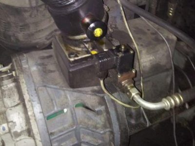
It is essential when installing a new compressor [1], to review the total air system. This is to ensure a safe and effective total system. One item which should be considered is liquid carryover. Installation of air dryers [3] is always good practice since properly selected and installed they can reduce any liquid carryover to zero.
It is good practice to locate an isolation valve close to the compressor and to install line filters [4].
|
|||||||||||||||||||||||||||||||||||||||||||||||||||||||||||||||||||||||||||||||||||||||||||||||||||||||||||||||||||||||||||||||||||||||||||||||||||||||||||||||||||||||||||||||||||||||||||||||||||||||||||||||||||
INSTALLATION / HANDLING 15
|
|||||||||||||||||||||||||||||||||||||||||||||||||||||||||||||||||
- If a circuit breaker is selected it should only be a magnetic trip type, set above the anticipated starting current of the machine, but below the maximum prospective fault current for the The circuit breaker or fuseable disconnect must be capable of breaking the prospective fault current at its terminals.
- PVC/PVC Type Calculated using the following conditions: PVC
insulated cable, armoured, copper conductors.
) Cable clipped to a wall, in free air.
- Ambient temperature of 40°C (104°F) and relative humidity of 40%.
- 20m (65ft) cable
- Volt drop limited to -10% during starting, -4% during normal
- Protected by the circuit breaker listed
16 INSTALLATION / HANDLING
|
If there are any deviations from the above, or special regulations apply, the installation must be planned by a competent, qualified engineer.
ELECTRICAL DATA
An independent electrical isolator or disconnect should be installed adjacent to the compressor.
Feeder cables/wires should be sized by the customer/electrical contractor to ensure that the circuit is balanced and not overloaded by other electrical equipment. The length of wiring from a suitable electrical feed point is critical as voltage drops may impair the performance of the compressor.
Feeder cables / wires connections to isolator or disconnect should be tight and clean.
The applied voltage must be compatible with the motor and compressor data plate ratings.
OPERATING INSTRUCTIONS 17
GENERAL OPERATION
The compressor is an electric motor driven, single stage screw compressor, complete with accessories piped, wired and baseplate mounted. It is a totally self contained air compressor package.
The standard compressor is designed to operate in an ambient range of 35.6°F − 104°F (2°C to 40°C). The maximum temperature is applicable to either version up to a maximum elevation of 3280ft (1000m) above sea level. Above this altitude significant reduction in maximum allowable ambient temperature is required.
Compression in the screw type air compressor is created by the meshing of two (male & female) helical rotors.
The air/coolant mixture discharges from the compressor into the separation system. This system removes all but a few PPM of the coolant from the discharge air. The coolant is returned to the cooling system and the air passes through the aftercooler and out of the compressor.
|
|
Cooling air is moved through the coolers by the cooling fan and discharged from the machine.
By cooling the discharge air, much of the water vapour naturally contained in the air is condensed and may be drained from the downstream piping and equipment.
The coolant system consists of a sump, cooler, thermostatic valve and a filter. When the unit is operating, the coolant is pressurized and forced to the compressor bearings.
The compressor load control system is automatic on−off line. The compressor will operate to maintain a set discharge line pressure and is provided with an auto restart system for use in plants where the air demand varies sufficiently to allow a compressor to shut down and save power. Significant system volume will assist this and is recommended.
Safety of operation is provided as the compressor will shut down if excessive temperatures or electrical overload conditions should occur.
18 OPERATING INSTRUCTIONS
COMPRESSOR CONTROLS
Direct online starting:
The compressor is equipped for Automatic Start & Stop Control. When the receiver tank pressure reaches the factory pre−set maximum pressure, the pressure switch stops the unit. When the receiver tank pressure drops below the factory pre−set minimum. The pressure switch resets and restarts the unit.
The pressure switch cover can be removed by unscrewing the two screws holding the cover.
Pressure switch adjustment:
The compressor package will cut−in and cut−out at factory preset pressure settings. Adjust the pressure switch only if absolutely necessary.
Adjustments are to be carried out only when the switch is mounted, under pressure and voltage−free.
When the receiver tank pressure reaches the factory pre−set maximum pressure, the pressure switch stops the unit. When the receiver tank pressure drops below the factory pre−set minimum, the pressure switch resets and restarts the unit.
DUAL CONTROL
|
|
Select either automatic start and stop control or constant speed control by adjusting the knob on the auxiliary valve. For automatic start and stop control, turn the knob on the auxiliary valve fully clockwise to disable the auxiliary valve. The pressure switch will then start and stop the unit.
| Auxiliary Valve. |
| A. Knob |
| B. Clockwise |
| C. Counterclockwise |
|
|||||||
Select constant speed control if the unit restarts in less than 10 minute intervals or runs more than 40 minutes per hour. Turn the knob fully counterclockwise to run the unit continually.
|
AUTOMATIC START & STOP CONTROL
OPERATING INSTRUCTIONS 19
- PRESSURE GAUGE
Indicates the system pressure.
PRIOR TO STARTING
- Make visual check of the machine, ensure that all guards secure and that nothing is obstructing the proper ventilation of, or free access to the
|
- Check coolant Add if necessary.
- HOURMETER
Records the total running time of the compressor.
- STOP BUTTON
When depressed will stop the compressor immediately.
- ON PUSH BUTTON SWITCH
When depressed will cause the unit to start and run in a loaded condition if there is a demand for air. If there is no demand, the machine will stop automatically.
- POWER ON INDICATOR LIGHT (Green)
Indicates the presence of control voltage.
- FAULT INDICATOR LIGHT (Red)
Indicates machine is stopped due to fault condition (high temperature or motor overload).
- Make sure air discharge valve is
- Turn on electrical isolator or The Power on (5) indicator will light, indicating that line and control voltages are available.
- Check direction of rotation at initial start or following interruption in power supply.
STARTING
- Press the START button. The compressor will start and then load automatically.
NORMAL / EMERGENCY STOPPING
- Press STOP button (3) and the compressor will stop
- Turn off electrical isolator or
20 MAINTENANCE
|
|
. It should be noted that the intervals between service requirement may be significantly reduced as a consequence of poor operating environment. This would include effects of atmospheric contamination and extremes of temperature.
The SERVICE/MAINTENANCE CHART indicates the various components’ descriptions and the intervals when maintenance has to take place. Oil capacities, etc., can be found in the INSTALLATION / HANDLING section of this manual.
Compressed air can be dangerous if incorrectly handled. Before doing any work on the unit, ensure that all pressure is vented from the system and that the machine cannot be started accidentally.
Ensure that maintenance personnel are properly trained, competent and have read the Maintenance Manuals.
Prior to attempting any maintenance work, ensure that:−
. all air pressure is fully discharged and isolated from the system. If the automatic blowdown valve is used for this purpose, then allow enough time for it to complete the operation.
. the machine cannot be started accidentally or otherwise.
. all residual electrical power sources (mains and battery) are isolated.
Prior to opening or removing panels or covers to work inside
a machine, ensure that:−
. anyone entering the machine is aware of the reduced level of protection and the additional hazards, including hot surfaces and intermittently moving parts.
. the machine cannot be started accidentally or otherwise.
Prior to attempting any maintenance work on a running
machine, ensure that:−
. the work carried out is limited to only those tasks which require the machine to run.
. the work carried out with safety protection devices disabled or removed is limited to only those tasks which require the machine to be running with safety protection devices disabled or removed.
ROUTINE MAINTENANCE
This section refers to the various components which require periodic maintenance and replacement.
. all hazards present are known (e.g. pressurised components, electrically live components, removed panels, covers and guards, extreme temperatures, inflow and outflow of air, intermittently moving parts, safety valve discharge etc.).
. appropriate personal protective equipment is worn.
MAINTENANCE 21
. loose clothing, jewellery, long hair etc. is made safe.
. warning signs indicating that Maintenance Work is in Progress are posted in a position that can be clearly seen.
Upon completion of maintenance tasks and prior to returning the machine into service, ensure that:−
. the machine is suitably tested.
. all guards and safety protection devices are refitted and correctly working.
. all panels are replaced, canopy and doors closed.
. hazardous materials are effectively contained and disposed of in a manner compliant with local or National environmental protection codes.
Repeat this procedure to get coolant to proper level when up to operating temperature.
When the unit is shut down, coolant will usually fill up sight glass. Do not adjust level based on level at shutdown. Proper level is always set for a running unit at operating temperature.
COOLANT CHANGE PROCEDURE
It is better to drain the coolant immediately after the compressor has been operating as the liquid will drain more easily and any contaminant will still be in suspension.
|
- Stop the machine, electrically isolate and vent all trapped
- Place a suitable container close to the drain
- Slowly remove fill
TOP UP COOLANT PROCEDURE
- Slowly remove fill
- Pour coolant into spout until spout almost
- Replace and tighten oil fill
- Start unit for about 10 seconds (until coolant drains out the bottom of the sight glass).
- Slowly remove fill
- Re−fill into spout until spout almost
- Replace and tighten oil fill
- Run
- Remove plug from drain
- Open the drain valve and drain coolant into
- Close the drain
- Replace plug in drain
- Refill the machine following the ”top up coolant” procedure After initial fill, to purge any airlocks, the machine should be run for a few minutes cycling between load and no load, before checking that the level is correct.
- Replace and tighten fill
COOLANT FILTER CHANGE PROCEDURE
- Stop the machine, electrically isolate and vent all trapped
|
- Loosen filter with the correct
- Remove the filter from the
- Place the old filter in a sealed bag and dispose of in a safe way.
- Clean the mating face of the housing taking care to avoid any particles entering th
- Remove the new Ingersoll Rand replacement filter from its protective
- Apply a small amount of lubricant to the filter
- Correct at operating temperature
- Too much
- OK
- Too little
- Screw the new filter down until the seal makes contact with the housing, then hand tighten a further half
- Start the compressor and check for
en
22 MAINTENANCE
AIR FILTER ELEMENT CHANGE PROCEDURE
- Stop the machine, electrically isolate and vent all trapped
- Unscrew the retaining cap and withdraw the old
- Fit the new
- Replace the retaining
SEPARATOR ELEMENT CHANGE PROCEDURE
- Stop the machine, electrically isolate and vent all trapped
- Loosen separator element with the correct
- Remove the element and place it in a sealed bag and dispose of it
- Clean the mating face of the
- Remove the new Ingersoll Rand replacement element from its protective
- Apply a small amount of lubricant to the element
- Screw the new element down until the seal makes contact with the housing, then hand tighten a further half
- Start the compressor and check for
BELT CHECKING AND ADJUSTMENT PROCEDURE
Check belt tension occasionally, especially if looseness is suspected. A quick check to determine if adjustment is proper may be made by observing the slack side of the belt for a slight bow when the unit is in operation. If a slight bow is evident, the belt is usually adjusted
satisfactorily.
A belt tension measurement device can be used to determine the tension of the belt.
Belt tensioning can be achieved by loosening the airend anchor screws, a belt tensioning bolt is provided to aid in moving the airend.
Follow the procedures outlined below to correctly set and measure belt tension.
- Lay a straight edge across the top outer surface of the belt drive from pulley to
- At the center of the span, perpendicular to the belt, apply pressure to the outer surface of the belt with a tension Force the belt to the deflection indicated in the table below, and compare the reading on
|
the tension gauge to the figures shown.
|
|
||||||||||||||||||||||||||||||||||||
COOLER CLEANING PROCEDURE
- Stop the machine, electrically isolate and vent all trapped
Ensure the pulley and sheave are properly aligned and the motor anchor screws are adequately retightened prior to restarting the compressor.
|
- Remove the top cover to obtain access to the cooler.
- Clean the cooler.
- Rebuild in reverse order.
TROUBLE SHOOTING 23
| PROBLEM | CAUSE | REMEDY |
| Compressor fails to start | Mains power or Control voltage not available. | § Check incoming power supply.
§ Check the control circuit fuse. § Check the transformer secondary windings for the control voltage. |
| Defective Star / Delta timer. | § Change Star / Delta timer. | |
| Machine shuts down periodically | High airend temperature. | Top up coolant. |
| Motor overload. | § Set overload to correct value and switch to manual reset. | |
| Line voltage variation. | § Ensure voltage does not drop below 10% on start up and 6% running. | |
| High current draw | Compressor operating above rated pressure. | Set pressure to correct rating for machine. |
| Separator element contaminated | Change air filter, and separator element. | |
| Low voltage. | § Ensure voltage does not drop below 10% on start up and 6% running. | |
| Unbalanced voltage. | Correct incoming supply voltage. | |
| Damaged airend. | † Change Airend. | |
| Low current draw | Air filter contaminated. | Change air filter. |
| Compressor operating unloaded. | Set pressure to correct rating for machine. | |
| High voltage. | Reduce site voltage to correct operating voltage. | |
| Defective inlet valve. | † Fit inlet valve service kit. | |
| High discharge pressure | Defective or incorrect pressure switch setting. | Replace or set pressure to correct rating for machine. |
| Blowdown valve defective. | † Fit blowdown solenoid service kit. | |
| Inlet valve malfunction. | † Fit inlet valve service kit. | |
| Low system air pressure | Separator element contaminated. | Fit new Separator element. |
| Incorrect pressure switch setting. | Set pressure to correct rating for machine. | |
| Minimum pressure valve malfunction. | † Fit Minimum pressure valve service kit. | |
| Blowdown valve defective. | † Fit blowdown solenoid service kit. | |
| Drive belt slipping. | Fit new belt. | |
| Air system leaks. | † Fix leaks. | |
| Inlet valve malfunction. | † Fit inlet valve service kit. | |
| System demand exceeds compressor delivery. | Reduce demand or install additional compressor. | |
| Compressed air filters contaminated.. | Replace air filter elements. |
NOTES:
- Must be carried out by a competent electrician.
† This work is recommended to be carried out only by an Ingersoll Rand authorized service technician.
24 TROUBLE SHOOTING
| PROBLEM | CAUSE | REMEDY |
| Compressor trips due to over temperature | Compressor operating above rated pressure. | Set pressure to correct rating for machine. |
| Package pre−filter blocked. | Clean / replace package pre−filter. | |
| Cooler blocked. | Clean cooler. | |
| Missing or incorrectly fitted enclosure panels | Ensure that all enclosure panels are correctly fitted | |
| Low coolant level. | Top up coolant and check for leaks. | |
| High ambient temperature. | Re−site compressor. | |
| Restricted cooling air flow. | Ensure correct air flow to compressor. | |
| Excessive coolant consumption | Separator element leak. | Fit new Separator element. |
| Blocked separator element drain. | † Remove fittings and clean. | |
| Compressor operating below rated pressure. | Set pressure to correct rating for machine. | |
| Coolant system leak. | † Fix leaks. | |
| Excessive noise level | Air system leaks. | † Fix leaks. |
| Airend defective. | † Change Airend. | |
| Belts Slipping. | Replace belt and tensioner. | |
| Motor defective. | † Replace motor. | |
| Loose components. | † Retighten loose items. | |
| Shaft seal leaking | Defective shaft seal. | † Fit Airend shaft seal kit. |
| Pressure relief valve opens | Defective switch or incorrect pressure switch setting. | Replace or set pressure to correct rating for machine. |
| Minimum pressure valve malfunction. | † Fit Minimum pressure valve service kit. | |
| Blowdown valve defective. | † Fit blowdown solenoid service kit. | |
| Inlet valve malfunction. | † Fit inlet valve service kit. | |
| Pressure relief valve defective. | Check the setting of the pressure relief valve and the rated pressure. | |
| Black residue on belt guard/cooler box | Drive belt slipping. | Replace belt and tensioner. |
| Pulleys misaligned. | Re−align pulleys. | |
| Worn pulleys. | † Replace pulleys and belt. | |
| Safety valve blows when compressor goes on load. | Minimum pressure valve stuck closed. | Strip minimum pressure valve, examine and repair if necessary. |
| Safety valve faulty. | Check the setting of the safety valve and the rated pressure. |
NOTES:
- Must be carried out by a competent electrician.
† This work is recommended to be carried out only by an Ingersoll Rand authorized service technician.
V SERIES 5-11 KW
50 Hz
Parts catalogue
ENCLOSURE 1
| CCN | CCN | ||||||
| ITEM | CCN | QTY | DESCRIPTION | ITEM | CCN | QTY | DESCRIPTION |
| 1 | 23790264 | 1 | f!T[fi PANEL, FRONT | 8 | 24038556 | 1 | i:pB] V MIDDLE PANEL |
| 2 | 23845266 | 1 | ft:[fi ,PX LEFT PANEL ASSEMBLY | 9 | 24003717 | 1 | J§[fi ,PXBACK PANEL ASSEMBLY |
| 3 | 23845274 | 1 | k:f[fi ,PX RIGHT PANEL ASSEMBLY | 10 | 39917489 | 6 | J1i BOLT M6X16 |
| 4 | 23889611 | 1 | ffm�� GUARD, BELT | 11 | 96742689 | 10 | J1i BOLT M6 X 16 |
| 5 | 22481501 | 1 | tat� TIMER | 12 | 96737564 | 8 | Jf.J NUT M6 |
| 6 | 24000697 | 1 | ff[fi V PANEL, TOP | 13 | 18983221 | 6 | fl_9 LATCHES KEY |
| 7 | 24000721 | 2 | L± V PILLAR | 14 | 23889587 | 1 | 5{Z M COVER, CONTROL PANEL |
)X:@ AIR DUCT SYSTEM 2
| CCN | CCN | ||||||||
| ITEM | CCN | QTY | DESCRIPTION | ITEM | CCN | QTY | DESCRIPTION | ||
| 1 | 18983320 | 1 | /Eir� DOWEL | 8 | 96745559 | 4 | �ill WASHER M6 | ||
| 2 | 23889579 | 1 | )XWjL FAN PANEL | 9 | 23979461 | 1 | �»)XJL BLOWER V5 225X80 | ||
| 3 | 24001844 | 1 | )XWj�)’t FAN COVER | 99319337 | 1 | �»)XWj BLOWER V7/11 250X80 | |||
| 5 | 92368687 | 2 | ��[fi§;&J1i BOLT | FLANGE,M6*1 | 10 | 23981012 | 1 | �)X� CONE ED2 225 | |
| 6 | 96737564 | 8 | Jf.J NUT M6 | 99319345 | 1 | �)X� CONE ED2 250 | |||
| 7 | 96742689 | 1 | J1i BOLT M6 X 16 | ||||||
ii� FILTER SYSTEM 3
| CCN | CCN | ||||||
| ITEM | CCN | QTY | DESCRIPTION | ITEM | CCN | QTY | DESCRIPTION |
| 1 | 23951981 | 1 | 2 | 95235156 | �fff CLAMP |
7t� SEPARATOR SYSTEM 4
| CCN | CCN | |||||
| ITEM | CCN | QTY | DESCRIPTION ITEM | CCN | QTY | DESCRIPTION |
| 1 | 22388045 | 1 | ffi7t�� OIL FILTER 5 | 95025466 | 1 | O-RING(7t�;C*fSEP STEM) |
| 2 | 24015778 | 1 | ±JLffi7t�;C*f OIL SEPARATOR ROD 6 | 95022133 | 1 | O-RING(7t�;C*fSEP STEM) |
| 3 | 54403266 | 1 | �ntf.1[3(�� ELBOW 1/4BSPT-6MM 7 | 99331803 | 1 | iJirP� @ffi CHECK VALVE |
| 4 | 92788959 | 1 | �ntf�� NIPPLE 1/4BSPT-6MM 8 | 92490358 | 0.3m | �ft� FLEXIBLE PIPE 6MM |
�� BASE SYSTEM 5
| CCN | CCN | |||||||
| ITEM | CCN | QTY | DESCRIPTION | ITEM | CCN | QTY | DESCRIPTION | |
| 1 | 14081962 | 2 | J1i BOLT M10×80 | 8 | 96702402 | 4 | J1i | BOLT M8 X 50 |
| 2 | 19012681 | 3 | btJgJZ� PACKAGE SUPPORT | 9 | 96704408 | 2 | J1i | BOLT M8X20 |
| 3 | 22419923 | 4 | �ftt� PAD | 10 | 96704416 | 4 | Jf.J | NUT M8 |
| 4 | 23889520 | 1 | fi’�JZ� | PLATE, BLET | TIGHTEN | 11 | 96740188 | 4 | �Jt | WASHER M8 WIDE |
| 5 | 24000671 | 1 | JL_§�� | BASE | 12 | 96702261 | 3 | J1i | BOLT M8X35 | |
| 6 | 24000689 | 1 | ±JL�� | MOTOR BASE | 13 | 96726971 | 4 | �Jt | WASHER M20 |
7 39138490 6 /Eir� DOWEL
fi’l:l ADJUSTING SYSTEM 6
| CCN | CCN | |||||||||
| ITEM | CCN | QTY | DESCRIPTION | ITEM | CCN | QTY | DESCRIPTION | |||
| 1 | 22420376 | 1 | �� NIPPLE 1/4 NPT X 6MM | 8 | 99328965 | 1 | lliiJ{Z PRESSURE GAUGE | |||
| 2 | 92788959 | 1 | �ntf�� NIPPLE 1/4BSPT*6MM | 9 | 99331696 | 1 | fi’l:l� VALVE 5.8BAR-6.8BAR | |||
| 3 | 92715051 | 1 | �ntf.1[�� NIPPLE 1/8BSPT*6MM | 10 | 92354539 | 1 | �� NIPPLE 2-1/4 BSPT | |||
| 4 | 54403266 | 1 | �ntf.1[m�� EBOLW 1/4BSPT*6MM | 11 | 92490358 | 0.4m | �ft� FLEXIBLE PIPE 6MM | |||
| 5 | 70278999 | 1 | lliiJff� PRESSURE SWITCH 7BAR 85 12 | 92490358 | 0.6m | �ft� | FLEXIBLE | PIPE | 6MM | |
| 7 | 96742689 | 2 | J1i BOLT M6 X 16 �� FLANGE 13 | 92490358 | 1.6 | �ft� | FLEXIBLE | PIPE | 6MM | |
fi’l:l ADJUSTING SYSTEM 7
|
||||||||||||||||||||||||||||||||||||||||||||||||||||||||||||||||||||||||||||||
CCN CCN ITEM CCN QTY DESCRIPTION ITEM CCN QTY DESCRIPTION
8 96738828 2 +’¥f:�JH CROSS BOLT M5 X 1 15 96742689 2 J1i BOLT M6X16 ��FLANGE
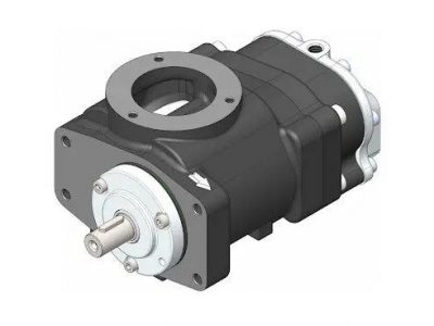
±JL AIREND SYSTEM 8
| CCN | CCN | |||||||
| ITEM | CCN | QTY | DESCRIPTION | ITEM | CCN | QTY | DESCRIPTION | |
| 1 | 23790298 | 1 | ±JL AIREND CE55C | 5 | 96702816 | 2 | J1i | BOLT M8*16 |
| 2 | 23889595 | 1 | ±JLJZ� FEET AIREND | 6 | 96702824 | 4 | J1i | BOLT M8*20 |
| 3 | 39416128 | 1 | tffJ:tff� TEMPERATURE SWITCH | 7 | 96704416 | 2 | Jf.J | NUT M8 |
| 95952388 | 1 | :7�� OUT JOINT | 8 | 96727573 | 2 | !jfi�ill WASHER M6 | ||
| 22141295 | 1 | ���� WIRE JOINT | 9 | 96728316 | 4 | �illM8 WASHER SPRING | ||
| 4 | 39404165 | 1 | O�ill O-RING | 10 | 96740188 | 4 | �Jt WASHER M8 WIDE | |
| 11 | 23951999 | 1 | ffi� OIL FILTER | |||||
CCN CCN ITEM CCN QTY DESCRIPTION ITEM CCN QTY DESCRIPTION
1 22471817 1 :it��� BAFFLE INLET 4 42684795 2 �Jt,:it�� GASKET, INLET
2 23983794 1 :it��,PX VALVE INLET NO 5 54403266 1 �ntf.1[m�� EBLOW1/4BSPT*6MM
3 36889608 4 J1i BOLT M8*25 6 92490358 1.3m �ft� FLEXIBLE PIPE 6MM
tt COOLING SYSTEM 10
| CCN | CCN | ||||||
| ITEM | CCN | QTY | DESCRIPTION | ITEM | CCN | QTY | DESCRIPTION |
| 1 | 22186688 | 1 | J£ tff�� PLUG TCV | 12 | 92106210 | 1 | .1[�� NIPPLE MALE 3/4BSPT |
| 2 | 22186696 | 1 | !jf� tff�� SPRING TCV | 13 | 92255934 | 1 | .1[�� NIPPLE 3/4″ BSPT |
| 3 | 22305965 | 1 | �� NIPPLE | 14 | 95052379 | 1 | .1[�� NIPPLE .75SAE X .5T |
| 4 | 22456214 | 1 | tff��* TCV | 15 | 95647889 | 1 | -=iff TEE .75SAE x .5T |
| 5 | 22463368 | 1 | tff��;C ELEMENT TCV | 16 | 95938122 | 2 | .1[�� NIPPLE .75SAE X .5T |
| 6 | 22856991 | 1 | �� tff��;C DUCT ELEMENT TCV | 17 | 95992822 | 1 | .1[m��,EBLOW .75SAE X .5T |
| 7 | 23986946 | 1 | tt� COOLER 5.5kw | 18 | 95993523 | 1 | .1[�� NIPPLE.56SAE X .5T |
| 23986953 | 1 | tt� COOLER 7.5-11KW | 19 | 96737564 | 4 | Jf.J NUT M6 SERRATED | |
| 8 | 24012064 | 1 | X� FLEXIBLE PIPE D .50 X 26″ | 20 | 96742689 | 3 | J1i BOLT M6 X 16 �� |
| 9 | 24012080 | 1 | X� FLEXIBLE PIPE 1/2″ X 11″ | 21 | 99331662 | 1 | J$}lliiJ� MPCV |
| 10 | 24012056 | 1 | X� FLEXIBLE PIPE D .50 X 16″ | 22 | 85560290 | 1 | FLEXIBLE PIPE D .75 X 24″ |
| 11 | 23060726 | 6 | 1� LINER 1i}�37J:t (.500″�) |
3′.� SAFTY SYSTEM 11
| CCN | CCN | |||||||
| ITEM | CCN | QTY | DESCRIPTION | ITEM | CCN | QTY | DESCRIPTION | |
| 1 | 19036185 | 1 | -=iff�� TEE | 3 | 99332009 | 1 | SAFTY | VALVE 8.8/7 BAR TANK |
| 2 | 19036219 | 1 | SAFTY VALVE 8BAR 7BAR UNIT | 22431761 | 1 | SAFTY | VALVE 10/8 BAR TANK | |
| 99332009 | 1 | SAFTY VALVE 8.8BAR 8BAR UNIT | 22431779 | 1 | SAFTY | VALVE 12.2/12 BAR TANK | ||
| 18990762 | 1 | SAFTY VALVE 11BAR 10BAR UNIT |
JL MOTOR 12
| CCN | CCN | |||||||||
| ITEM | CCN | QTY | DESCRIPTION | ITEM | CCN | QTY | DESCRIPTION | |||
| 1 | 23990930 | 1 | JL | MOTOR | 5.5KW | IP23 | 3 | 96705116 | 4 | J1i BOLT M10×50(5.5KWffl) |
| 23990948 | 1 | JL | MOTOR | 7.5KW | IP23 | 92280981 | 4 | J1i BOLT M10×30 | ||
| 23990955 | 1 | JL | MOTOR | 11KW | IP23 | 4 | 96726633 | 4 | !jf��ill SPRING WASHER M10 | |
2 92061498 4 �ill WASHER M10 5 18983874 4 MOTOR PAD (ONLY 5.5kW MOTOR)
�}J TRANSMISSION SYSTEM 13
| CCN | CCN | ||||||
| ITEM | CCN | QTY | DESCRIPTION | ITEM | CCN | QTY | DESCRIPTION |
1 89296552 1 ffm BELT PK5 1050 2 99331720 1 SHEAVE AIREND 7.5KW-7 BAR
5.5KW-7 BAR 99332165 1 SHEAVE AIREND 7.5KW-8 BAR
|
||||||||||||||||||||||||||||||||||||||||||||||||||||||||||||||||||||||||||||||||||||||||||||||||||||||||||||||||||||||||||||||||||||||||||||||||
89296560 1 ffm BELT PK5 1080 99332181 1 SHEAVE AIREND 7.5KW-10 BAR BAR BAR
BAR
BAR BAR
� CONTROL SYSTEM 14
| CCN | CCN | ||||||||
| ITEM | CCN | QTY | DESCRIPTION | ITEM | CCN | QTY | DESCRIPTION | ||
| 1 | 24024051 | 1 | � ,PX | CONTROL BOX | ASSEMBLY | 3 | 99331894 | 1 | ffJLii:H START BUTTON |
| 24024069 | 1 | � ,PX | CONTROL BOX | ASSEMBLY1 | 4 | 19007277 | 1 | )<:�lfl7F):J FAULT LIGHT | |
| 2 | 19007269 | 1 | �lfl7F):J | POWER LIGHT | 5 | 99331886 | 1 | �JLii:H SHUTDOWN BUTTON | |
R�’E SERVICE KITS
CCN ITEM CCN QTY DESCRIPTION
38339297 ffJLlf1’E START MAINTENANCE
99332785 l�’E MAINTENANCE KIT(3000,6000,9000)
18983254 :it�� VAVLE INLET DOL
18983262 J$}lliiJ� MPCV
42595710 miR�’E SHAFT SEAL MAINTENANCE